Experiments with high speed spindles
Here's a random collection of pics. I appreciate that there's almost no detail here.E-Mail me if you'd like to know more.
From the vey beginning I wanted to build/buy a high speed spindle for the router. At 20,000 rpm with a single flute carbide cutter you can machine Al at 2m/min. A handy thing if your machine isn't rigid enough to handle big cutters.
At first I was a little intimidated at the thought of making an acurate spindle. it turns out that it's not that hard.
To skip the history lesson and go directly to the spindle that I currently use go here
Now the first question you should ask yourself before taking on a construciton project is "Can I just go out and buy one of these?". A retail purchase is nearly always the cheapest and easiest way. So I went looking:
 |
Routers are the most prolific choice for cnc builders, they come in a variety of sizes, have either a 1/4" or 1/2" collet chuck and plenty of powere. A mate, in a similar quandry
, went out and bought a chinese router for AU$50 and it notched up >50hrs of run time before developing some end float. Pretty good in my book. There is, however, one problem with them; they run on universal AC motors and are deafeningly loud! I just can't handle that much noise in my shed, and I suspect my neigbours would agree. |
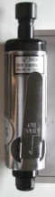 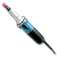 |
There are a few flavours of die grinders out there, The electric ones ar basically routers with better
bearings, so they're out. There are some little air grinders, about 5/8" diameter which run fairly quietly. OK so my compressor souns like a machine gun but we'll ignore that.
Unfortunatley they have very little torque. a 1/8" burr is a big cutter for these things. |
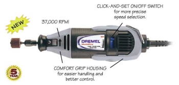 |
A mainstay of the teeeny weeny cnc community and probably in a category of it's own. Yes it has a universal motor and makes a bit of noise. But it doesn't make a LOT of
noise. There are a lot of tools available for it. The problem is that the bearing that supports the chuck is a long way back from it, and securely mounted in soft plastic. This is actually a problem with a lot of the aforementioned options, vey few have good, metal, mounting points. A really good page on running a dremel as a spindle |
So I decide to have a go at building one.
For a motor I pick an inrunner brushless RC motor. These things are used in model airplanes and, if you can get the heat away from them, will deliver a LOT of power. The one I have is good for 300W peak!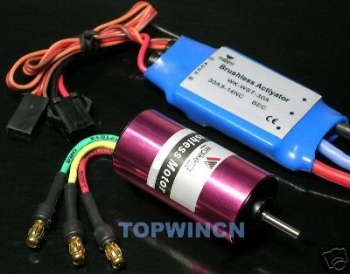
Motor and brushless controller from ebay for about AU$75
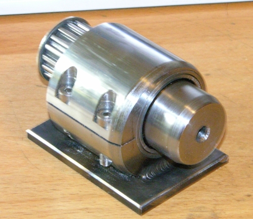
The basic layout of the thing is very simple
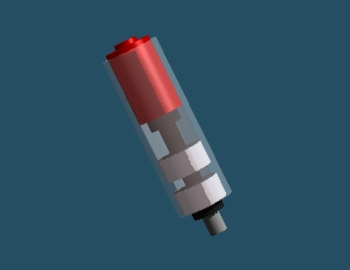
Note the double bearings down the bottom. This is VERY important in a spindle as, even if the shaft and body are made of the same metal, one will heat up before the other. If the bearings are too far apart, differential expansion will change the amount of preload on them. The famous example of this is the sherline 10000 rpm spindle which ships with less preload because of this.
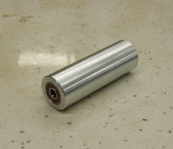
I machined the end to take Dremel collets and used a Dremel nut. The internal taper and bore for the collets was made by just plunging a center drill in. Simple as...
The end result is good. It spins at 35,000RPM and has lots of power (I run it from an ATX power supply). For bearings I used medium quality skate bearings. These are the cheapest deep groove bearing you can get. For some reason, the skate heads will pay for ABEC7 grade bearings so these are available for the sorts of monies your average teenager will part with. I think I bought a tube of 8 for $20... See below for what I paid for a pair of bearings from a bearing shop. Because the shaft is only 8mm these bearings ar small and can handle speeds up to 100,000RPM.
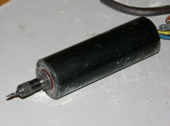
Skip forward a couple of years and this spindle didn't get a lot of use. Lining everything up and getting the power out of that tiny motor shaft (3mm) was harder than it looked. At 100W load that thing got bloody hot and things expanded, bearings seized and it became generally unhappy.
I guess, those model airplane engines don't make good spindle drives as they are really designed to run for short periods of time with a very big fan (ie a propeller) cooling them.
Hard to find one that will deliver the power you need(and I reckon that's about 300-400W continuous duty) without requiring a very high current 12v power supply too.
For engraving or really light duty work they may hava a place. Though I'd need to do some more development before I'd call this design a goer.
Anothers attempt at it
A friend purchased an excellent little spindle from Wolfgang Engineering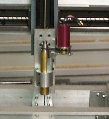
He powered it with a brushless motor and it really looked good. I believe now that a belt driven spindle is realy the best way to go. You don't have to worry about alignment, or the motor heating the bearings, and it makes swapping parts our a heap easier.
His experience with this spindle mirrored mine though, the small size (only a 1/8" collet) and low power turned out to be too limiting for him and he abandoned the spindle.
Helllooooo Feature Creep
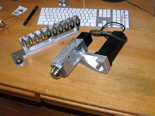
Whilst all this was going on, I got the CNC Router finished and picked up the 200W die grinder you can see on the router page .That, and some very valuable experience gained using a friends router, convinced me that I needed an automatic toolchanger. I'd had this in the back of my mind for some time having seen that inspirational bit of work by Home Shop Accessories.
Having built the little 35KRPM unit I started out with a bit more confidence.
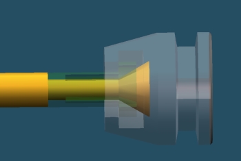
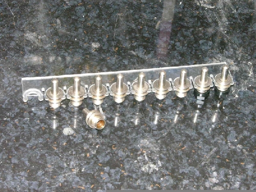
As you can see much of the design effort was focussed on the gripper that grabs the pull stud on the back of the toolholder.
As a first attempt I decided to try a simple, spring collet. This (and the spindle shaft) was machined from some 4140 and slit with a dremel. After some tricksy internal work the whole thing just clicked into place!
The bearings are 15x35x something angular contact types. I picked them up from a bearing shop for the bargain price of AU$68 for the pair.
Considering that I can buy a Chinese angle grinder, that has a double row, preloaded, angular contact bearing from the local hardware store for $25 I was more than a little dissapointed with this price..
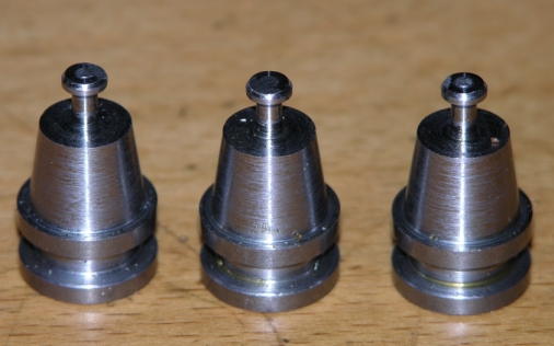
The toolholders are made from 16mm diameter 1030 mild steel on a CNC lathe in 3 minutes and are so cheap I'll probably not harden them, just throw them away with the tool..
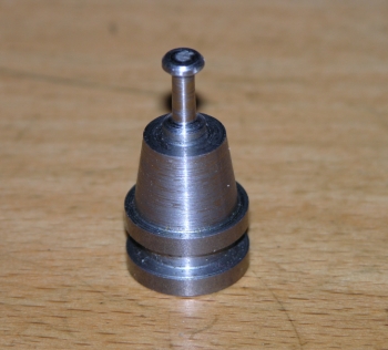
I initially made the pull stud quite long to give me some alignment slack. Turned out to be unecessary, the rev B toolholders are shown below:
It takes 30Kg to compress those belleville washers the 3mm it takes to release a tool. So I'll probably use a 25-30mm diameter pneumatic ram, built into the body of the mount.
I'm building a variant of the mill spindle speed controller with a USB interface and will use a 150W servo motor to run the thing.
...To be continued.............
Continuing...
What I ended up using on the cnc router is a 250W die grinder I picked up from ebay: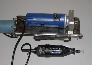
This thing did about 15KRPM and would just about push a 1/4" cutter through alumninium at 800mm/min.
Boy was it LOUD! Both the motor and tool noise were just too much. In the end, it just had to go.
The next attempt was a 200W DC servo motor with a bearing mount grafted on. I used a collet donated from a friends dead router.
Angular contact bearings were used and the whole thing was quite rigid.
This worked surprisingly well. It was whisper quiet and probably more rigid than the other setup.
Problems here too though, at 2500RPM I could only cut at 100mm/min.
For those not across the whole speed and feed thing, it goes a bit like this:
- We want each tooth of our little endmill to be taking a cut between 0.5% and 1% of the cutter diameter each time it hits the job. Given that your average hobby router has about a poofteenth (that's a metric poofteenth BTW) of the rigidity of
a mill, we'll try to stay around the 0.5% mark.
- With a 6mm, 2 flute, cutter, this works out to 0.005 x 6 x 2=0.06mm per revolution of the tool.
- So at 2500RPM That tool should be moving at 2500 x 0.06 = 150mm/min
Now I can cut at that speed on my mill, so, with this spindle, the router had no real speed advantage.. Clearly a compromise was in order...
The compromise
This is a pair of angular contact bearings with a simple spindle, Preload is maintained by a bolt clamping the pulley down.
Note the lack of a collet. I've recently completed a set of tool holders for the mill, all of these secure the tool by means of a single grub screw. It works much better than you'd think.
The hole is simply reamed to size.. Try it, you'll be surprised..
Anyhow, this mounts up like this:
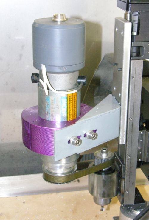
Inside the plastic bit is a 2 pulse per rev (ie one pulse per cutter rev) encoder
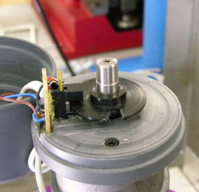
This feeds back to Mach 3 and allows it to slow the feed rate if the cutter gets bogged down.
So far I'm happy with this setup. I can live with the noise, and cut at 200mm/min. I'm going to try some 3 flute cutters and another 1000RPM, just to see what effect these have...
Stay tuned...
It's been a while..
I did a bit of tweaking with this spindle. It ended up looking like this: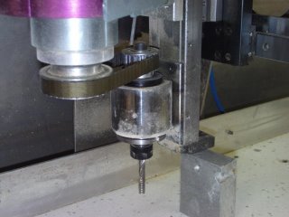
The important details are:
- The ER11 collet. I purchased a set of collets and a nut for about AU$150 from Ebay. A little pricey but well worth it. Machining the spindle nose to suit was a snap on the CNC lathe
- The large flywheel/nut. I found that adding this large mass increased the rigidity of the spindle significantly. In essence I had a gyroscpically stabilised cutter!
A better shot of the flywheel.
Initially I drove this with a timing belt and 2:1 ratio pulleys, This gave a spindle speed of around 5000 RPM and I could cut Al at 400mm/min. But there was a little runout in one of the pulleys and this resulted in some vibration which irritated me.
About this time a group I'm part of undertook a belt conversion project for some X2 sized mills. They came out pretty good:
The belts we used were Gates 5M types. I have the same one on my 3/4HP lathe and it's run for years. They guy who turned the pulleys was kind enough to make me up a set for the spindle:
With a 3:1 ratio I now had something like 8000 or 9000 rpm (I never did get around to measuring it). This gave me 600mm/min in Al with an acceptable noise level...
And so it was for a long time...
That spindle did an absolute mountain of work. At 8000RPM the bearings were probably doing more than they were rated for. Certainly after about an hour of running the spindle was too hot to touch. So was the motor!I would have kept this spindle for ever.... honnest... but I started doing more and more batch runs of parts, particularly circuit boards, and my yearning for a toolchanger took hold once more...
It started with an impulse buy of a 500W brushless servo motor on EBay. I found a drive (also on ebay) and got them to my door for AU$200 all up. A pretty good deal I reckon!
I got lucky too. The motor manufacturer sent me the motor datasheet and I was able to download the servodrive (an Alan Bradley Ultra 3000) software from a site. Had these things not happened, I'd have ended up with a white elephant. There are a LOT of wires to connect from that motor to the drive.
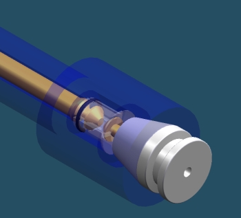
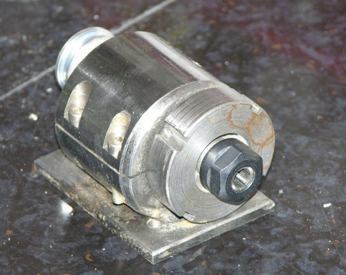
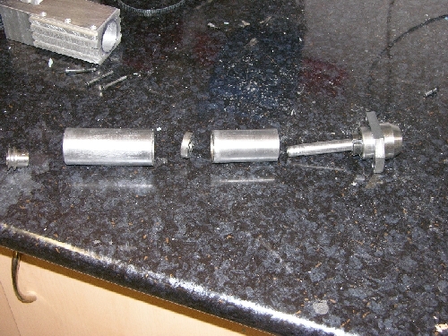
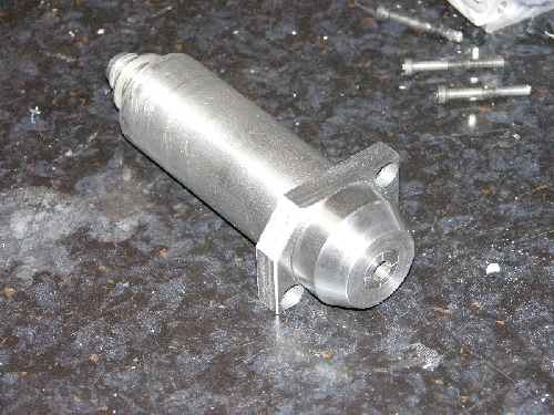
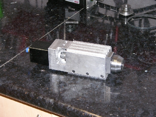
I was determined to put everything I'd learned about spindle design into this one, here's what I ended up with:
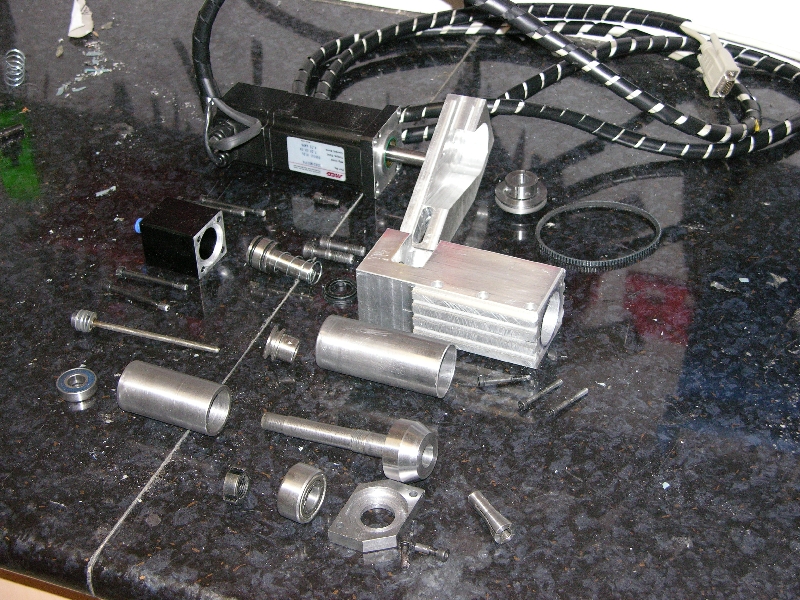
OK so there are a few parts..
I know it looks a bit confusing, I will endeavour to do some drawings and get them up here soon.
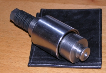
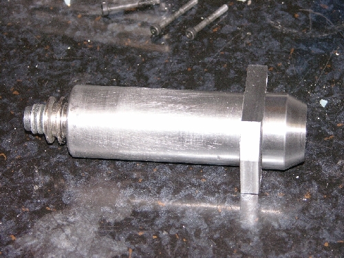
Starting with the spindle shaft. I turned it down from a bit of 4140 bar. I deliberatley kept as much mass in it as possible to reproduce the gyroscope effect of the previous model. One of the tricks with these jobs is to try to do all the machining in one go, without removing the part from the lathe. I almost managed it, but had to turn it around once to machine the collet taper. Even though I used a collet chuck in the lathe, I still ended up with 0.04mm runout. Now I use single flute cutters for the most part, so it's not such a big deal. If it does become a problem, then I'll mount a tool on the router table and remachine the taper in situe.. To get the bearing seats exactly right, I used a technique I first saw (I think) on the 5bears site. You machine the shaft with bearing seats that are a poofteenth oversize, then you take some fine emery cloth, spin it quick and taper the section until the bearing will just start to slide on. Blue the surface, fit the bearing and remove it, you can now see where the diameter is just too large. Take a thin strip of emery paper and just work on that spot. Re blue it, re fit and re peat. Eventually the bearing will be a perfect fit.
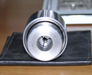
I used the same GCode that turned the collet taper in the spindle nose to turn the collet itself... OK I'll fess up. That collet took me 5 attempts and I destroyed 2 slitting saws making it. Not because it's particularly hard to make. But because I was rushing the job.. The collet is made from some 4140 bar too and has an 8mm reamed bore.
The drawbar is just a piece of M5 allthread rod with a bushing welded to the top to carry the Belville washers .
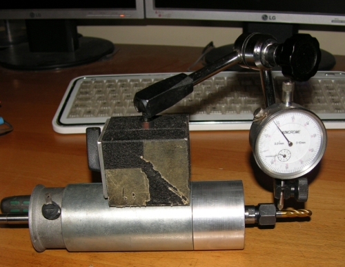
Once I got this far I lashed up a jig to measure the force the air ram would need to apply to release the tool.
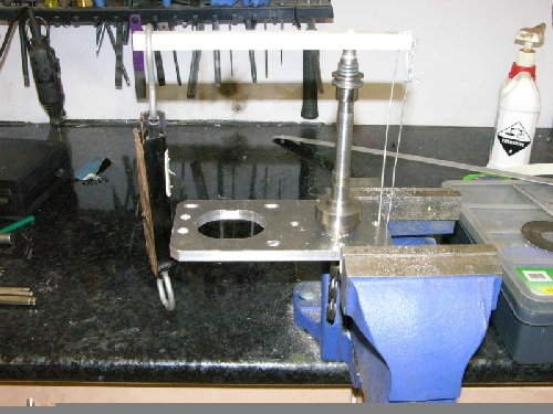
I then made the piston and cylinder. Only later to realise that I'd manage to stuff it up. So I made another one that generated twice the force and it worked a treat. So much for science!
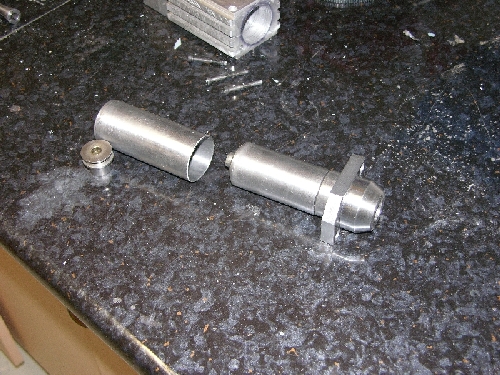
Next up is the main bearing. It's a double row, angular contact bearing that's preloaded and secured to the spindle shaft with a dinky castellated nut that I made. I may still end up with two, single row, angular contact bearings, I've allowed for them in the design.
Note that the spacer block, that slides into the spindle bearing case, means that the spindle is located almost entirely by that bottom bearing. The top bearing is only there to take the radial loading from the pulley. If the shaft gets hot, it can expand without generating any play. It makes more sense in these pics:
So now I had this spindle, I needed a mount for it.. I wanted to use a big block of Al, but these are expensive things. Jack and his furnace came to the rescue!
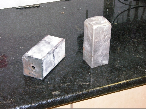
I welded a plate on the bottom of some SHS and we had a mould. Jack melted some scrap and we soon had a loaf of metal. I ended up using one and a half of these loaves for this project..
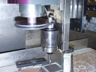
Next step was to make a reference surface:
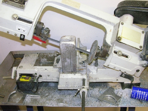
Geez I'm fond of that bandsaw! Note the use of a low profile clamp to secure that block to the table. The same group that did the pulley conversion for the X2's did those.
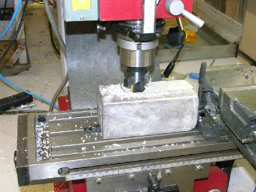
I finally got to use the X3 to it's rated capacity drilling a 25mm hole. (This is a joke. No standard X3 could do this I blew up the original motor trying and now have a 2HP 3phase motor with a sensorless vector drive, I still tripped it twice drilling this hole!)
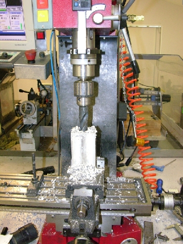
A few minor operations later and I had a mount!
This is the small cylinder
I made an arm to hold the motor and a very cool steel pulley with an integral split collar:
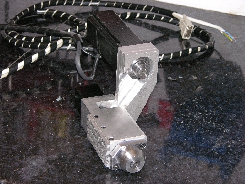
I ended up flipping the pulley around (collar on the top) this made for better alignment.
Toolholders
I made these out of some low carbon steel. First up I machined the shanks, then I flipped them (using a collet chuck in the lathe) turned the clip groove and roughed the theaded section and bore
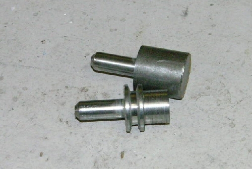
The thread and taper came next and I cut a clip strip from some polycarbonate sheet I had.
Initally I was going to use nylon or something similarly soft. I think the polycarbonate might just turn out to be the best way to go.
Finally I made a stand for them that inlcuded a simple tool length measuring device.
The idea is to measure the length of the tool every time we change. Two reasons for this:
1. I just hate tooltables. maintaining offsets and diameters against what you actually have in the rack is just a pain in the ass. When I'm in the middle of a job and I snap a tool. I really cant be bothered remembering to go through it all.
2. It will give the machine the opportunity to detect a failed toolchange.
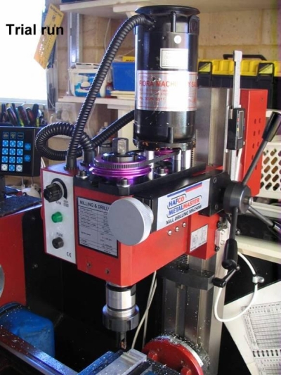
At last I had it on the machine. I wired and plumbed it all up and fired up the motor for the first time. I reckon it makes about half the noise at 10KRPM that the last one made at 8KRPM. So far so good.
I write a toolchange macro for Mach3 and (after only breaking two of the tool clips :-) it just works.. I can't beleive it, it just works! This morning I had it cycling through all the tools (well, the ones in the unbroken clips) for about 20 minutes and it didn't miss a beat..
Now the truth is that this spindle/toolchanger is yet to see what I'd call serious work (ie an hour or so cutting metal) but I have done some little jobs and the surface finish is really good. I cut at about 900mm/min and 0.5mm with a 6mm single flute carbide bit. With the cover down, you can have a conversation next to the thing and it's inaudible outside the shed.